Repacing the Off Side Floors and Sills
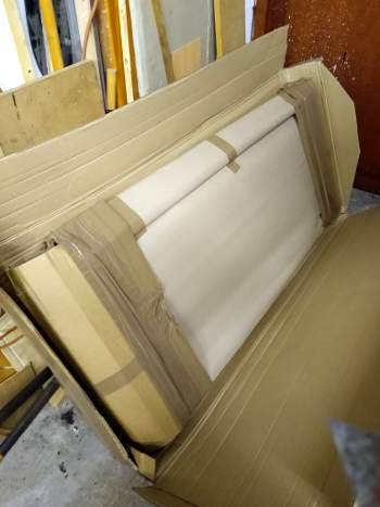
The panels arrived a couple of weeks after ordering them as some of the panels were made to order. They were well packaged with each panel wrapped in corrugated cardboard and then boxed together in a sturdy box.
The floor panels looked okay, though there were a few wrinkles around some areas, I assume the different grooves/depressions in the panel were pressed individually. Nothing too serious that a little panel beating wouldn't correct. Where the outer sill and jacking point were welded to the floor there was no rust protection on the welds. As this was a long term project and the panels were likely to be lying around for some time, I decided to clean them down and add a coat of Etch Primer. It will no doubt get scratched off during assembly, but that will be easier to clean up than the panels going rusty before they are fitted.


Now having the panels it was time to get busy with the grinder and start taking out the rust. This was just a case of area by area cutting out the panels without removing the flanges of the floors cross member and the rear passenger companion box. I will be replacing the door step but for the moment wanted to keep it in place as a reference for the location of the inner and outer sills.
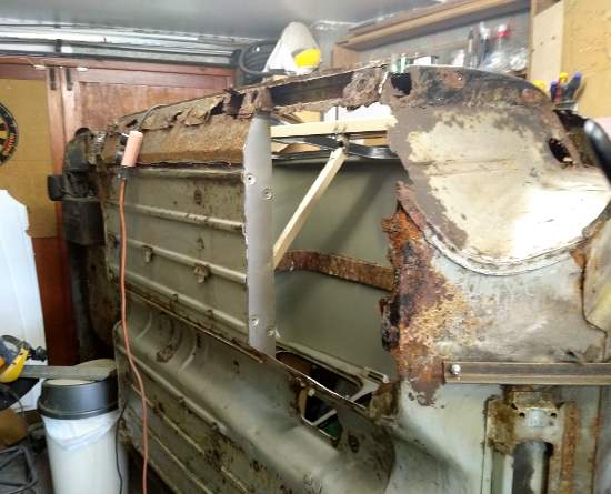
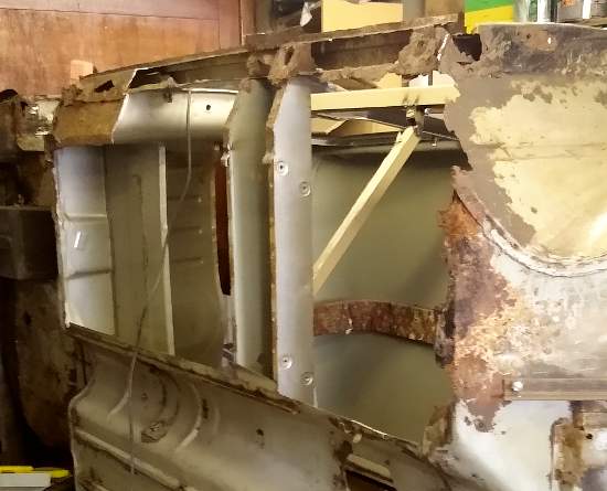
I was fortunate as the companion box flanges hadn't suffered any corrosion and it would be possible to clean them up and re use them. The outer section of the heel board was also removed ready for the new rear subframe mounting point repair panel. This did reveal a lot more work that would be needed around the rear wheel arch and boot floor.
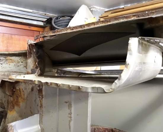
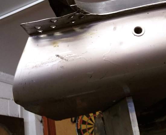
The floor cross member flanges were a different story, they had been twisted and damaged during the process of removing the spot welds and would need to be cutaway and replaced. I marked a line 100mm from the end of the cross member as a reference to measure from when fitting the new flanges.

The edge that lay between the floor and gearbox tunnel was tidied up by marking a straight edge with masking tape and carefully grinding back the metal to the tape.
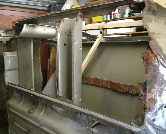
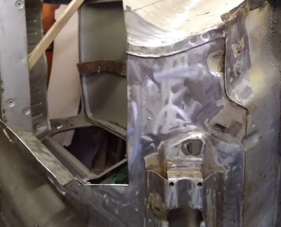
The metal around the front subframe mounting holes was badly corroded and a stress/fatigue crack had started to form. As this area of the kick board needed to be replaced, I first made a gauge by securing a sheet of steel with three Tek-screws then drilled through the existing holes from inside the body. The gauge could later be refitted to the repaired steel and used to redrill new subframe mounting holes in the correct location.
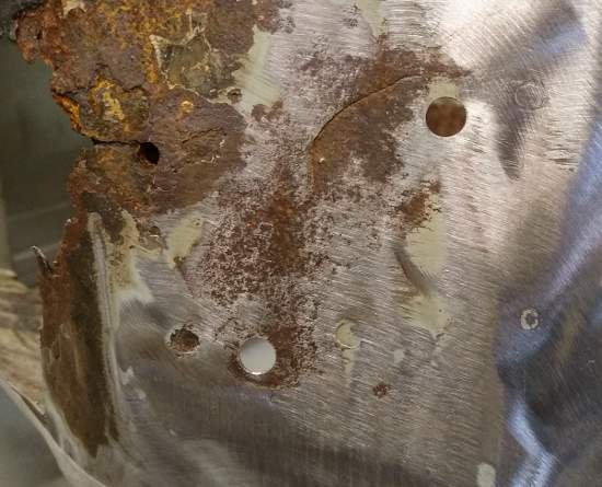
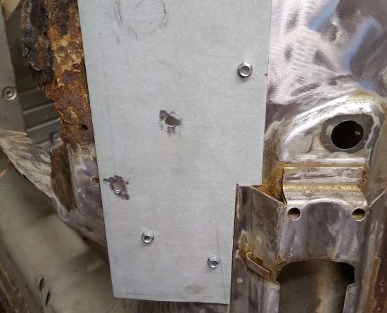
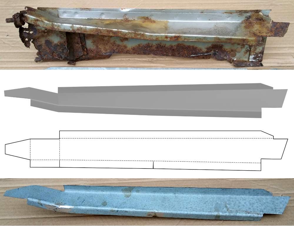
A part that I had overlooked whilst ordering panels was the companion box filler plate, which sits between the inner sill and rear wing filling the gap at the bottom of the companion box. It didn't look difficult to manufacture but the slope on the top surface of the plate meant it wasn't just straight folds. Part of the old filler plate had been removed with the inner sill so I measured this and recreated the part in Blender.
I then needed to unfold the part onto a flat plane in Blender without changing the shape of any of the tri / quad faces of the model. My first attempt was to use the Paper Model script which unfolds meshes and makes a template for recreating them out of paper. Whilst it unfolded the model accurately, it couldn't solve how to keep the pattern as a single unit and split it into different islands. In the end I manually unfolded the the model onto the X - Y plane using a combination of repositioning the 3D cursor and rotating edges. You can learn more about how to use Blender from my book 3D Computer Graphics Using Blender 2.80 - Modelling Methods, Principles & Practice
Finally I rendered the unfolded mesh with Freestyle marking the outer profile and bent edges with different line styles. The render was output at a 1 to 1 scale.
The Images below show the different stages from rusty part to finished filler plate.
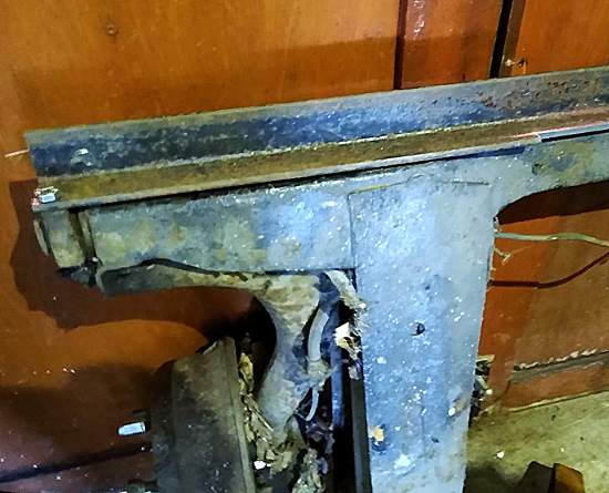
A trial fit of the floor pan made it obvious that I needed to repair the heal board before it could be correctly fitted. One of the problems I had was the existing subframe mounting points had previously been 'repaired' and the only original mounting point on the near side was the nut nearest to the boot floor panel.
I made a template for the mounting hole positions by drilling through the subframe mounting brackets which were still on the subframe, picking up the hole centres on a length of angle iron. The problem with this was the angle needed to have a clearance from the boot floor cutaway from the central area to clear the depressions in the boot floor.
Lots of lining up with straight edges and clamps and the heal board repair panel was welded in place.

The flanges on the companion box were cleaned up and new flanges welded onto the floor cross member. I could now do the first fit of the floor cutting it to fit the gearbox tunnel. I had purchased some but clamps which worked well along the edge with the gearbox tunnel, but hadn't got any Cleco type fastners. Fortunately I had a box of self drilling Tek-screws which were used to pull the panel tight through some of the plug weld holes.


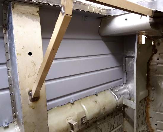
Knowing the floor would fit accurately, I now set to removing all the paint from the surrounding metal and inside box sections where there was a possibility of rust forming under the paint. Quite a laborious process using rotary wire brushes, poly strip disks and a DA sander.

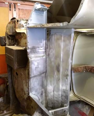
As belt and braces for the rust protection of the body, I then coated all exposed steel with Firtan rust treatment. I chose this based on past experience when I was in my 20's I had an old Mk1 minivan that I had done some work to but was rotting raster than I could keep up with. Whilst I had it, I replaced the rear subframe but the underside of the boot floor was red with light surface rust. I coated the floor with Firtan then brush painted primer and top coat over it. The van was used for a further five years then cut in half to make a trailer (if only I knew what they would be worth now) which was used for a further 5 years. After I finished with the trailer I gave it to my Dad who used it to transport manure for his allotment, he kept it at least 8 to 10 years. When he finally got rid of it the boot floor was still solid with no rust breakthrough.
This isn't an endorsement of Firtan, just my past observations. The treatment does need to be left to work for 48 hours if the temperature is below 20 ℃ which can make jobs drag on a lot longer than expected.


After a couple of days the treated steel was etch primed and any areas that I would no longer be able to get at such as inside box sections and flanges that would be plug welded were brush painted with Synthetic Truck Coat. Any paint that spills out of the hidden areas will be removed before finishing the paint job in case of reaction with future primer / top coat. I will remove the paint from and around plug weld holes before welding and along seams with an electric file. Some of the paint will burn away between flanges, but hopefully this will be better protection than bare metal to metal. The cavities will be coated with cavity wax after the bodywork is finished for even more protection.
The floor was then clamped back in place ready for welding, the only difference being I replaced the Tek-screws with 4mm set screws and nuts to make sure the flanges were pulled tight together.


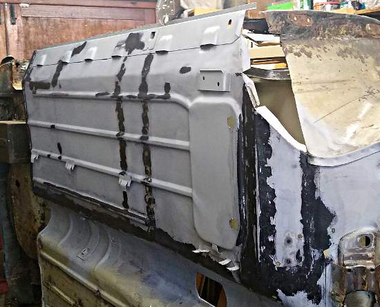
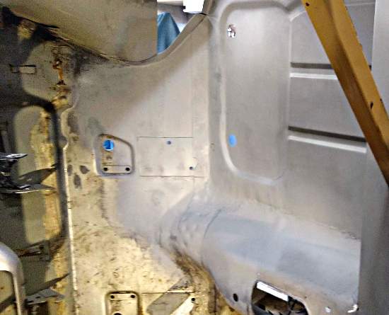
A lot of work to get here but the new floor and sill is finally welded to the heal board, gearbox tunnel, companion box and cross member. Still a lot of cleaning up to do but it is moving in the right direction.


My attention has now turned to fabricating a repair plate for the toe board. From what I could see on near side of the car, the floor and toe board have two large overlaps forming a double thickness angle at the front of the floor. The spot welds were also doubled up into two rows, I can only assume this is done to stiffen the front of the floor / toe board area, so I am recreating the same welding pattern on the repair.
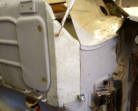
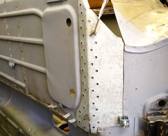
The repair panel was welded in place, remembering not to fill in the Tek-screw holes used for the subframe mounting point template. On the inside of the panel a new support plate was also welded to the toe board. The template was then refitted and new subframe mounting holes drilled.
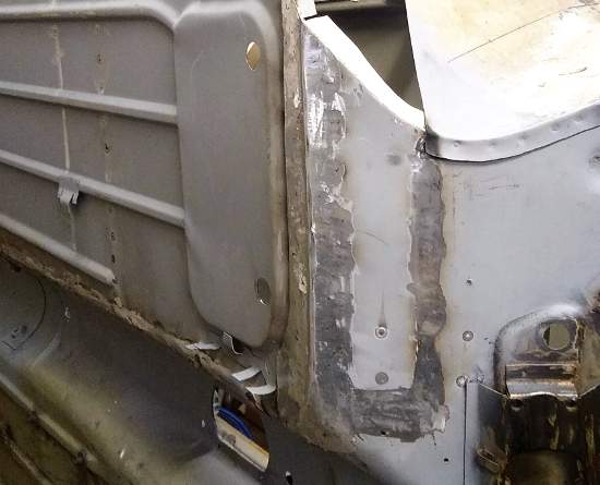

With the welding done, any areas of metal that had been left exposed or etch primer that had been affected by the heat of welding was wire brushed and treated with Firtan before repainting with etch primer.

More content coming soon
If you are interested in using Blender the free Open Source 3D creation suite for your own engineering or product designs, my book 3D Computer Graphics Using Blender 2.80 - Modelling Methods, Principles & Practice gives a detailed and structured introduction to using Blender for new or intermediate users.
The Book Contains
- Pages: 514
- Images: 924
More about the book, including a chapter by chapter breakdown can be found >> Here <<


