Tutorials Using Blender & Gimp
Blender has been the main tool in my creative arsenal for almost 20 years and having previously written a couple of books to help others learn Blender, I have decided to put my Blenders video and animation knowledge to the test and create a video Blender training course. Hopefully it will help new users and those wanting to learn a little more about Blender get a good understanding of how to use this incredible open source creative package.
Different Angle 3D
Different Angle 3D is the YouTube Channel where my video are held online. These pages will give you a link to each video together with a timeline of the different sections of each video. The videos build your knowledge as you work through them, so it is advised to watch them in sequence as you may miss key information in later videos if you haven't seen the previous ones.
Video Tutorials
- Getting Started (8 videos)
- Steel Frames & Fabrications
- From the Cube to a Barn (4 videos)
- Steel Stock Library (2 videos)
- Manual Plasma Cutting Table
- CNC Router Design & Build
Web Page Tutorials
Blender Books
Getting Started
The Different Angle 3D Getting Started section is made up of 8 videos totalling more thn 3.5 hours of video training. It starts with an introduction to the Different Angle 3D series and outlines what I hope to include in these videos, then goes on to walk you through the basic principles of mesh modelling in Blender and Blenders Interface.
Click the images below to go to the Different Angle 3D - Getting Started pages


Steel Frames & Fabrications
The Steel Frames & Fabrications section, starts the practical exercises of the tutorials. The section starts with a simple (Dutch) Hay Barn model, where you don't have to think about accuracy, just keeping proportions right so it represents what a barn would look like in a render or video. This should give any new user an easy introduction to modelling. The section then moves into designing with precision for real world component, showing how Blenders mesh modelling can create dimensionally accurate models which can later be manufactured in a home workshop. In the series, I hope to cover steel fabrications, machined components and models for 3D printing.
Following through the tutorials below will hopefully help you prove your design ideas in 3D before committing to cutting up any real materials.
From the Default Cube to a Barn
This is the first of the practical Blender videos where you can follow the steps and discussion in the videos and build your own (Dutch) Barn model. This is kept fairly simple to allow somebody completely new to mesh modelling get a feel of working in 3D space. The model is built from Blenders Default Cube and uses a reference image to help get the proportions of the barn to look right. Video 009 - Part 1 - Creating a Reference image in Gimp shows how the reference image was created from a couple of photos so you can create your own reference images.
If you would like to repeat the tutorial on your own computer, this reference image and other assets can be downloaded from >> Here << If you would like to help with the creation of these tutorials, a small donation for the download would be very much appreciated.
Click the images below to go to the Different Angle 3D - From the Default Cube to a Hay Barn page


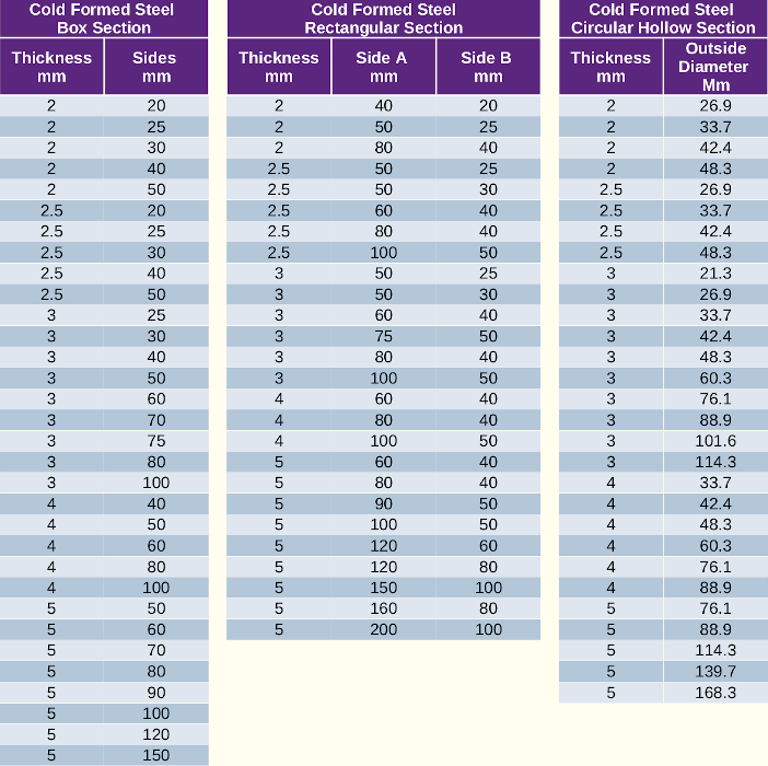
Building a Steel Stock Library
This is the first of the Blender Precision Modelling videos that shows you how to create a mesh model accurately to real world sizes. have chosen this as the first precision modelling tutorial as the different steel sections you create will be used in future videos about modelling steel fabrications.
Click the images below to go to the Different Angle 3D - Steel Stock Library page.


For anyone who doesn't want to take the excessive amount of time modelling their own steel stock profiles, I have uploaded mine to my Gumroad page and they are available for a small fee to help cover some of the costs involved in creating the video tutorials and maintaining the website.

The individual steel sections in the library are:

Subscribe to the Different Angle 3D YouTube Channel to get notifications when new videos for
this project are uploaded
By clicking >> Here <<
Design & Build a Manual Plasma Table - Work in Progress
The Plasma Table will be designed to real world units so the finished design can be built from elevation renders taken from the model. The steel sections used in the tutorial will be based on the standard steel profiles created in the previous Steel Stock Library.
The first 2 videos of the Plasma Table project are now online and more will follow soon.


Subscribe to the Different Angle 3D Youtube Channel to get notifications when new videos for
this project are uploaded
By clicking >> Here <<
Design & Build a CNC Router Table - Currently in the Early Planning Stage
It has been a long term aim of mine after building an early CNC Router Table back in 2020, to build a new updated one. Back then cheap components such as linear slides etc. weren't available, so with a very limited budget, the design was based around what scrap metal and cheaper components I could scrape together. Even the electronic stepper controller was designed and built on a wired breadboard.
Now with the availability of cheaper linear guide I am planning a build of a steel frame CNC router with linear guides and a OEM machine spindle rather than a AC Router.
Tutorials will follow as I progress with the CNC router project, but with other commitments and the planned tutorials above, it may be a while before the first of these videos appear. The image below shows the early stage of planning for this project.

Subscribe to the Different Angle 3D Youtube Channel to get notifications when new videos for
this project are uploaded
By clicking >> Here <<
Presision Modelling a 608 Bearing
 This was my first ever Blender tutorial, initially released for Blender 2.4x series of Blender back in April 2004. It was later updated to Blender 2.60 and then in April 2019 updated to Blender 2.80
The tutorial will walk you through the basics of modelling with precision with Blender and introduce you to the most commonly used modelling tools.
- Part 1 - Drawing the bearings cross section.
- Part 2 - Detailing and spin the bearing.
- Part 3 - Adding the Ball Bearings.
- Part 4 - Modelling the Bearing Cage.
- Part 5 - Cage Securing Clasp.
- Part 6 - The Dust Shield & Circlip.
Modelling a Realistic Propeller Blade
 This tutorial was written for Blender 2.70 series. It uses a background image of a propeller blueprint to create a series of sections through a propeller blade which are then skinned to give the propeller profile. The tutorial uses both curves and mesh objects.
The tutorial uses both curves and mesh objects.
Using Hooks to Deform a Curve
 This tutorial was written for Blender 2.63 series. It shows you how to use a Bevel Object on a curve to form a hose. It then takes you through the process of adding Hooks to the curve and parenting the hooks to the end fittings so the hose bends with the fittings when they are moved or animated.
The technique maintains good end tangency of the hose.
Blender Books
3D Computer Graphics Using Blender 2.80 Modelling Methods, Principles & Practice
 Learn to create 3D Computer models using Blender 2.80.
A guide to creating 3D computer models using Blender 2.80. A detailed reference to blenders modelling tools is followed by practical exercises to guide you through a step by step learning process. Working through the book you will create a low-poly house and a detailed Spiral Staircase. Concentrating on modelling principles, the book also introduces you to Blenders Materials, Textures, Lighting, Rendering and Animation.
The details of the book open in my Illustration website.
Blender Precision Modelling Guide
 A Guide to modelling parts and components accurately using Blender.
This book was written in 2007 for the Blender 2.43 and is now outdated.
The guide was created to assist Artists and Engineers, to learn the basics of mesh modelling of non deformable objects with Blender. It uses a structured approach to introducing Blenders tools and work-methods. The guide focused solely on Blenders Mesh Modelling capabilities, it ignored the myriad of animation, texturing and photo-realistic rendering tools and concentrated solely on getting started and producing accurate models suited for both artistic and engineering purposes.
Adventures In Blender >> A review of the Precision Modelling Guide
Now withdrawn, the contents are slowly being recreated in the newer tutorials and books above.


