Design and Build the Rotating Jig
As I am a little older and a lot lef flexible than I used to be when I worked on car body repairs, I decided that it would be well worth the effort being able to turn the minis body shell over, rather than me having to lie underneath it. You can buy rotating jigs but seeing I had a lot of suitable steel lying around i decided to make my own. I
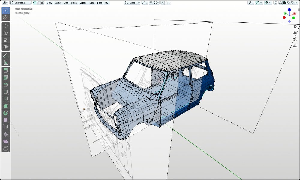
 The first stage was to make sure the mini body would clear the structure of the rotating frame and the easiest way of doing that was to rough out a mini body model in 3D using Blender and use that as the basis for designing the frame. A quick Google search for free Austin Mini blueprints brought up drawingdatabase.com which offered Free blueprints for creating 3D Models. Though I couldn't find a licence reference on drawingdatabase.com, both the page Title and meta-name indicated their drawings were offered as free.
A set of mini plans were downloaded, then using the open source image manipulation program Gimp, they were used to slice the plans into separate front, side, top and back views.

I now switched to Blender 2.80 and the separate images were loaded as reference images in Blenders 3D Viewport. The images were scaled so the dimensions on the image aligned to Blenders metric units. The images were then assigned to the respective view.

With the reference images in place it becomes an easy task to build the virtual body shell. By having the front, side and top views open in different viewports it is a quick and easy task to position vertices in the correct 3D space. With this method of using reference images it doesn't take long to go from the first quad to a completed body shell.
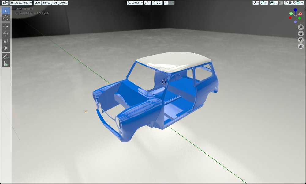
As I was only looking for basic measurements to construct a rotating jig, I wasn't going for a precision model that matched every curve of the Minis body panels. All I was looking for was a body shell roughly to size so I could check that when it was rotated on the jig, the extremities of the body didn't clash with any of the framework of the jig.

One of the great things about Blender 2.80 is you are not constrained to working in a viewport that is either wire frame or just basic shaders. With the Eevee real time render engin available in the viewport you can work in a fully rendered view.

With the body shell roughed out, my thoughts now turned to the design of the rotating jig. On early Minis the body shell was dipped in a vat of paint and to facilitate this a hole was provided through the bulkhead and seat back to hold the factories rotating framework. The first assumption was to centre the jig on the factory rotation point as you would assume this was near the centre of gravity of the body.
I had a couple of lengths of 70 mm x 40 mm x 3.5 mm folded steel channel that had been salvaged from a domestic lift shaft that would be used as the main support frames. I also had a collection of box section angle iron and round tubing available. As my workshop isn't that big the Mini needs to be moved from one side to the other so I have room to work, therefore the rotating jig needed to be on castors.
The first part of the process was to model the castors then the end frame. The Mini body was then positioned central to the frame and in front view its origin set central to the point of rotation. The body could then be rotated and raised so the extremities of the body shell cleared the framework.

Knowing the centre height of the jig I could now add the framework for rotational supports that attach the jig to the body.


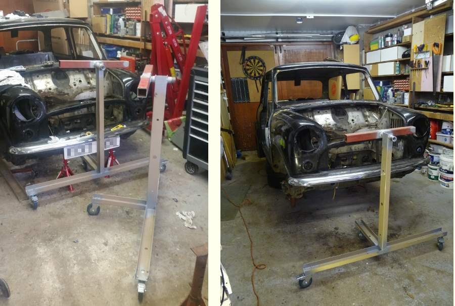
All that was left for me to do now, was to build the rotating jig based on the Blender design. The main frames were built first then the Mini jacked up so the centre of rotation matched the centreline of the Jigs. the connecting framework was then added and the axle stands removed.

Video opens in a new YouTube window.
In total the rotating jig has cost me £18.40 for the castors, a few bolts and a handful of welding rods. Being able to plan out the design in Blender has been invaluable.
 If you are interested in using Blender the free Open Source 3D creation suite for your own engineering or product designs, my book 3D Computer Graphics Using Blender 2.80 - Modelling Methods, Principles & Practice gives a detailed and structured introduction to using Blender for new or intermediate users.
The Book Contains
Pages: 514
Images: 924
More about the book, including a chapter by chapter breakdown can be found >> Here <<


