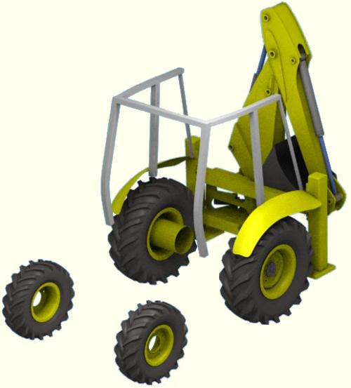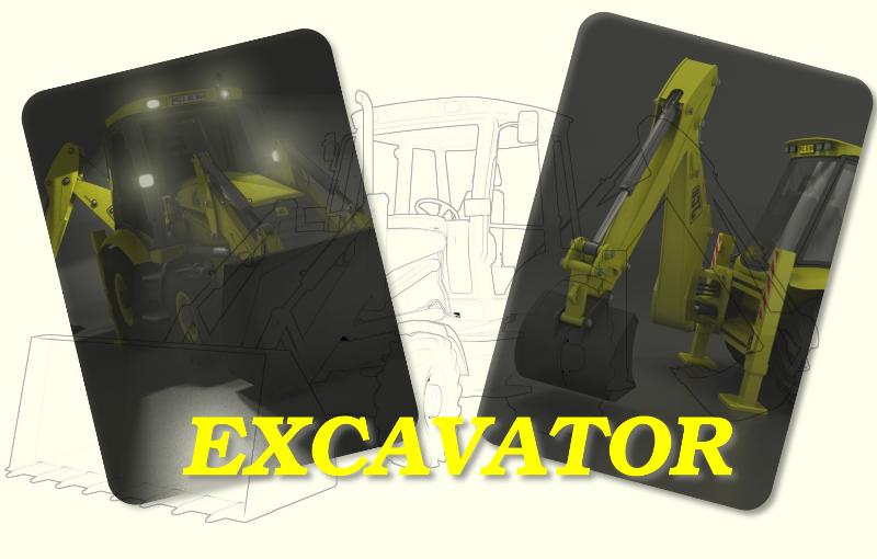
The Process of Modelling and Rigging a Mechanical Model
This project was carried out in 2008/2009 using Blender 2.48
I have been working on this model for some time now and rather than repeating the usual step by step tutorials I have decided instead to write a brief article. The article will detail the process and a few of the techniques used to get to get from the first idea to construct a complex mechanical model that could be animated, to the finished excavator.
As with any project the first stage is planning and as this was a learning exercise to get to grips with Blenders animation tools, I had to choose a machine that had a lot of moving parts. The excavator fitted the bill perfectly.
Now knowing what I was going to model it was time to go off and find reference materials. A set of plans would be useful but unfortunately non were available on the usual plan repositories, however the manufacturer did have some reasonable side, front and rear views in there pdf literature. They didn't exactly scale through from one view to the next but a little adjustment in Gimp got them near enough to be used.
Besides the plans Google was useful to find photographs and whilst passing a near by construction site an excavator was parked alongside the fence allowing me to have a close up look at the machinery.
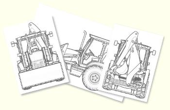
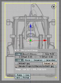

Setting up pans in blender is quite a simple process, I usually work from three 3D views and toggle the active view to full screen with Ctrl-down arrow. As I only had a front back and side view of the excavator these were set-up.
To set-up the views, In the 3D view header click View>Background Image and from the background Image window load the front view. To help align the other views drag a plane so the edges touch the extremities of the excavator front view. In the next 3D window load the back image and then use the X Offset, Y Offset and the Size controls in the Background Image window to scale and align the image to the edges of the plane. For the side view you will need to rotate the plane 90 degrees on the Z Axis and align the image only to the top and bottom edges.
Before I set about modelling the excavator I thought it would be useful to make sure I could get it to animate. To do this I simply traced the arms and buckets using Bezier Curves and used these as simple 2D cut-outs to help position the armatures.
The pistons and cylinders used simple Track To constraints with their ends parented to the respective component, in this case the cylinder to the arm and the piston to the fulcrum. The process is described really well in the Blender 2.3 Guide and is still relevant to the current versions of blender.
It should be stressed that pivot and rotation points must be accurately set and aligned using Blenders Snap tools.
The bucket movement was a little more complicated than a straight armature chain, requiring both ends of 3 bones to be set to fixed locations. This was achieved by adding an Armature Object at the pivot point of the fulcrum and parenting it to the arm; snapping the other end of the bone to the pivot point of the connecting rod. Another bone was extruded from this point and snapped to the interconnection between the Connecting Rod and Bucket. Then a third bone was extruded and snapped to the pivot point of the bucket. An empty was also added to the pivot point of the bucket and parented to the arm, so the empty would move in relation to the arm's movement.

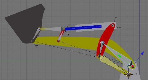
The Fulcrum was parented to Bone 1, the Connecting Rod parented to Bone 2 and the Bucket to Bone 3. The trick to getting this type of mechanism to work was adding an IK Constraint to Bone 3 with the target set to the empty I had placed on the Bucket pivot point, with Use Tail selected in the IK Constraint.
The two unused axis of the bones were disabled in the Armature Bones panel allowing the bones to only rotate on the one axis. To animate the bucket movement now only required Bone 1 to be rotated in Pose mode and all the other components would follow.
The front mechanism used a similar set-up on both the front bucket rotation and the top cylinder fulcrum.
Satisfied that the process of animating this machine could be accomplished it was time to start modelling.
If you have read through the Precision Modelling tutorials you should be familiar with all the tools and techniques needed to create any mechanical models.
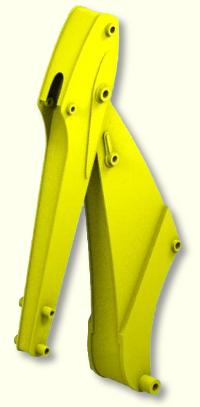
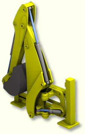
In fact its even simpler to create a model for animation as it only needs to be a representation of the real thing and not a CAD perfect 3D reproduction.
The process is therefore simply a matter of tracing areas of the model from the background image in one view and then pulling the vertices to align with the corresponding point in the perpendicular view.
The job is made even easier because the Tractor unit and front mechanism is symmetric between the left and right sides, so only one side needs to be modelled with the other being created using a Mirror Modifier.
On complex models working component by component can be a lot less daunting than trying to build the whole model as one mesh.
