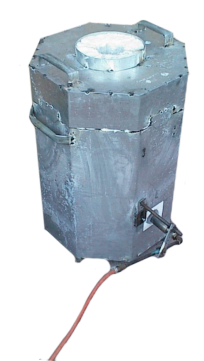
Over time I intend to detail some of my old engineering projects, which include the construction of a tool and cutter grinder from a cheap drilling machine and various other tools and foundry equipment.
CNC Ronter Project 1999-2000
Back in 2007, I thought it would be good to get into an upgrade/rebuild of my old (1999-2000) CNC router. which was originally made from available materials on a shoe-string budget. A lot of the design work for the CNC router upgrade had been completed and the design has been used to demonstrate the use of Blender as a hobby 3D CAD design package in the Blender Precision Modelling Guide.

The problems of my first CNC machine are detailed below and theirs a lot that can be done to improve its performance without breaking the bank and investing in linear guides, ball screws and proprietary stepper motor drives. This project is to see if I can make a low friction version of the existing machine using readily available parts or components that can be made on my Chester Model B lathe/miller and castings produced with the small furnace I made the other year.
Design Peramiters
- Use as much of the old machine as possible. The Bed, 18mm BDMS guides etc.
- Replace the guide bushes with V rollers to reduce friction.
- Design a simple roller nut to remove the friction from the leadscrews.
- Utilise 608 bearings wherever possible, available from skateboard suppliers much cheaper than bearings from mainstream bearing suppliers.
- Keep the components simple and small enough to machine on my Chester Model B and using castings made in my home foundry.
- Design the components and assembly using Blender producing a series of tutorials based around the machines components to help others get to grips with producing accurate 3D models and assemblies with Blender.
- Investigate other drive electronics, possibly a bipolar chopper driver.
The problems with my first CNC Router
My first attempt at a CNC router detailed below has some major limitations in its design and performance. Notably it was built on a shoestring budget with the cheapest possible configuration. The bed was made from bonded aluminium box section. These were architectural trims acquired at cost price. This has proved to be sufficiently rigid and provides good fixing via the ‘T’ slot sections. This is possibly the most successful part of the machine. Most of the other parts of the structure were machined from a length of 3inch by 1 1/2 inch extruded aluminium bar, where this wasn't big enough sections were bolted together.

The guides are lengths of 18mm bright drawn mild steel rod with sintered bronze bushes as the slides. Again the 18mm diameter bar has proved amply rigid enough for this size of machine, however the friction from the bushes causes a sufficient “slip stick” effect to be a problem and light oil on the guides quickly becomes contaminated with dust binding up the slides and causing the stepper motors to lose steps. The machine then loses position and messes up the job.The positioning of the carriage is carried out using lead-screws made from threaded rod with brass nuts. To minimize backlash a split nut tightened by a small grub screw was used.
The threaded rod was easily accurate enough to position the router within 0.1mm of the intended position, but backlash was a problem and as the backlash was adjusted out friction increased again causing the stepper motors to lose steps. The electronics was also a problem. Not something I have a great deal of experience in I managed to trawl the web and put together a basic stepper drive but extremely inefficient and not capable of fast step rates. The motors relied on dropping resistors to regulate the power resulting in much poorer performance than could be achieved with better electronics.
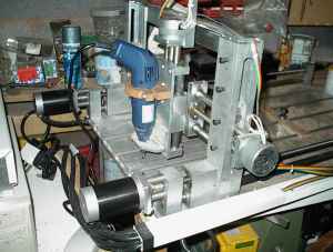
My First CNC Router
The machine bed was made from epoxy bonded aluminium extrusions and the support components machined from 3 x 1 1/2 solid bars. The design of a traveling bridge and twin X-axis drives was chosen to allow larger pieces to be mounted on the table without requiring extra torque to drive them. The Y-axis guides can be raised within the frame to accommodate thicker pieces. The machine performed well on slow feed rates but occasionally missed steps on the X-axis when the feed rate was increased it seemed obvious larger motors were required. After some searching I found a suitable replacement with the same frame size but a substantial increase in torque. A slight modification was made to the coupling to accommodate the increased shaft diameter and the new motors fitted. The machine hasn't missed a beat since. The step generator circuit was built using a simple TTL logic circuit. This gave the correct 4-phase sequence of steps for the stepper motors from the serial step signal generated by the computer. The output from the TTL circuit was then used to control the power transistors to the motors.



Small Home Foundary Project
This page is a record of the progress I am making setting up and using a hobby aluminium foundry. Don't copy what I am doing it can be very dangerous and requires a lot of knowledge and experience to do it safely.
Before considering any of this you must first read my Terms of Use page.
One of the most common methods of producing casting moulds is using green sand. This is where a mould is formed by ramming green sand (a blend of sand and clay) around a pattern, the pattern is then removed leaving a hollow recess the shape of the casting. For anything more than the most basic of castings it becomes necessary to use a two piece mould, with the sand being formed to the required shape in a cope and drag. It's always best where possible to use a metal cope and drag which will not burn, but often in hobby foundries wood is used as it is more readily available and affordable. In this case extra care must be used to prevent molten aluminium coming into contact with the wood where it could cause both fire and dangerous fumes.
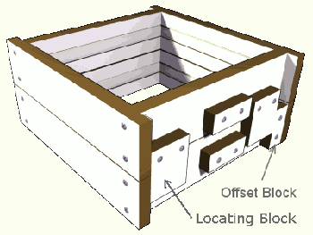
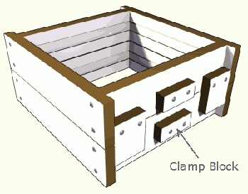
One of the requirements of the cope and drag is that they are aligned accurately together and can only fit one way (the cope shouldn't fit if it is rotated through 180 degrees). This is achieved by having the Offset Block in one corner of the Drag and making the Locating Blocks a snug fit against the corners of the drag and the offset block.

To stop the cope floating off the drag when metal is pored into the mould the two halves can be clamped together using G-Clamps over the Clamp Blocks.
The simple design here can be adapted to suit any size of Cope and Drag and can be made from any suitable available wooden board.
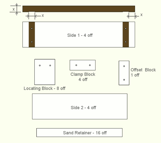
The length and height of each side can be any dimension to suit casting size you require. Side one however should be longer than required by four times the thickness of the wood you are using (dimension X above).
The sand retainer strips are made from thinner material; I have used 3mm hardboard. The sand retainers are pinned to the inside of the cope and drag to stop the cope and drag lifting off the sand when they are being turned over.
The sides should be glued and screwed together. If the board you are using has a facing material that won't accept glue, this should first be removed from the glue joint areas. All other components can be secured firmly with screws onto the outside of the cope and drag.

