Modelling the Dust Shield and Circlip
In the Outliner deselect the eye icon of the 608-Cage.002 and select the eye icon of the 608-Race.
The 608-Race should now be the only object visible in the 3d Viewport. Click on the race to select it.
Press Num3 to go into side view and Z to open the Shading menu and choose Wireframe.
Tab into Edit Mode and LMB select the top inner vertex of the rebate arrowed below.
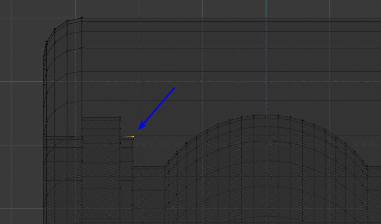
Press Shift-D to duplicate the selected vertex then P to separate it from the 608-Race object.
Tab into Object Mode and LMB select the new Vertex Object (608-Race.001)
Tab back into Edit Mode and LMB select the single vertex. The vertex is placed on the inside outer edge of the shield.
Num/ into Local View and Extrude the vertex on the Z axis -0.75

Then to set the centre point for the first radius of the shield Extrude Y -0.35
Snap the 3D Cursor to this vertex. then select the bottom right vertex
Click on the Spin Icon in the Tool Panel and spin the selected vertex:
- Steps: 7
- Degrees: 60

Extrude the end vertex on the Y axis -0.775
Select the vertex under the 3D Cursor and x Delete it.

Select the vertex at the bottom of the ark and snap the 3D cursor to it.
LMB select the end vertex and Rotate it -60 degrees
Press Ctrl-I to invert the selection, then Shift-D to copy the selected vertices and move them to the side.
Rotate the selected vertices through 180 degrees.

On the 3D Viewport Header click on the Snap drop-down and choose vertex snap.
Ensure the Magnet Snap icon is also selected.

Grab the selected vertices and move them below the deselected vertices.
Then Grab them again and move the mouse cursor close to the bottom vertex of the deselected edges

The selected edges will snap to the deselected edges.
Select All and from the RMB menu select Remove Double Vertices

As we have rotated some of the vertices their Normals will be pointing in the opposite direction, to correct this press Shift-N Make Normals Consistent.
Num/ out of Local View, then Num1 for front view and Z choosing Solid view. The Race, Balls and Cages will be back in the viewport.

LMB select the bottom vertex and Grab moving on the Z axis allow the vertex to snap onto the top surface of the inner race.
Again Grab the bottom vertex and move it on the Z axis 0.05 to add some clearance between the shield and the inner race.

Ensure the 3D Cursor is positioned on the bearings centre.

Press Z and choose wireframe then select the Spin Icon on the Tool Panel. Click on the blue handle of the spin widget to open the Spin Panel
In the Spin Panel set:
- Steps: 64
- Angle: 360
- Auto Merge: On
- Axis Y: 1
- Axis Z: 0
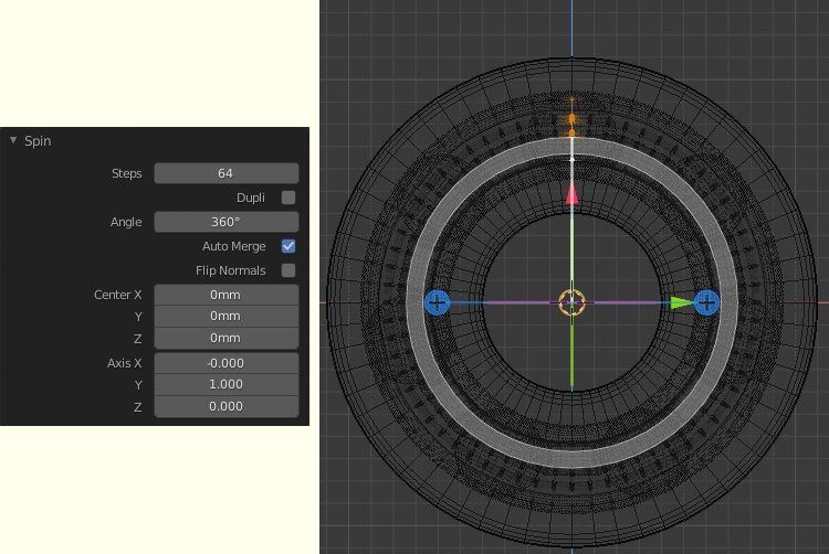
Press Num3 to go into Side View and select All
The inner face of the Shield has bee created, we now need to give it some thickness.
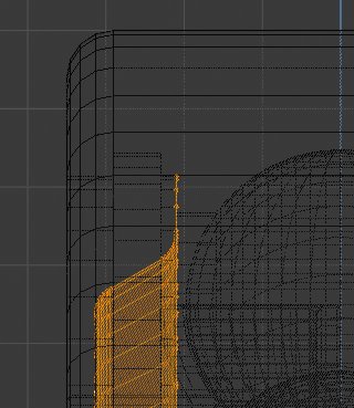
On the Properties Window choose the Spanner Icon to open The Modifier panel.
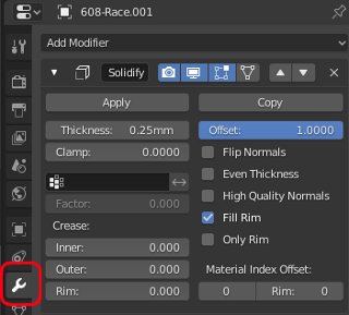
Click on Add Modifier and from the Generate list choose Solidify.
In the Solidify modifier panel set:
- Thickness: 0.25
- Offset: 1
the Shield will now have a thickness of 0.25 but no vertices on the front face
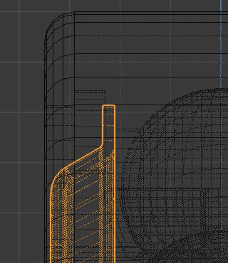
Tab into Object Mode and press Apply at the top left of the Solidify Modifier Panel.
The Modifier will be removed and the front face will now be a mesh with vertices, edges and faces.
Press Num/ to go into local view for the Shield and Tab back into Edit Mode.

In Edge Select mode Shift-Alt-LMB select the 4 edge loops around the inside and outside edges.
RMB click to open the Context Sensitive menu and choose Bevel Edges then LMB click to open the Bevel Panel.
In the Bevel Panel set:
- Width 0.05
- Segments:1
the shield will now have chamfered edges.
Tab into Object Mode and Shift-D to duplicate the shield then Esc to leave it in place.
We can now mirror the duplicated shield across the bearing. Press Ctrl-M for mirror then Y for the axis and LMB to accept.
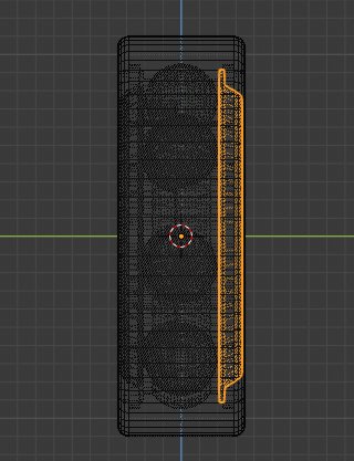
The two shields have now been created, but as they were created from 608-Race their names have been assigned as 608-Race.001 and 608-Race.002.
n the Outliner double click on 608-Race.001 and change its name to 608-Shield.001.
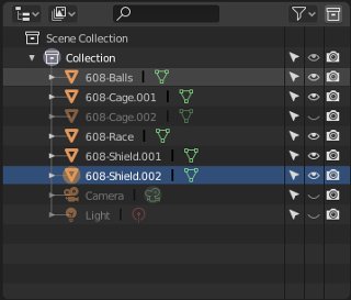
Then double click on 608-Race.002 and change its name to 608-Shield.002.
The two Shields are now created and positioned within the rebate of the bearing race.
The last components to produce are the Circlips that hold the Shields in place.
Select the 608-Race object and Tab into Edit Mode

LMB select the top right vertex of the circlip groove.
Press Shift-D to copy the vertex then Esc to leave it in place.
Press P (Part) to separate the vertex to a new object which will be named 608-Race.001.
Tab into Object Mode and select 608-Race.001
Tab back into Edit Mode for the new object.
Select the single vertex and Extrude it on the Y axis 0.4mm
Select All so both vertices are selected then Extrude on the Z axis -0.75mm

A new face will be created. As we only need the vertices and edges press X to open the delete menu and choose Only Faces.
We will be left with 4 edges and vertices that can be spun around the bearings centre to form the Circlip.
Press Num1 to go into front view and click in the Spin icon of the Tool shelf. LMB click on the Blue spin handle to open the Spin Panel and set:
- Steps: 64
- Angle: 360
- Axis Y: 1
- Axis Z: 0
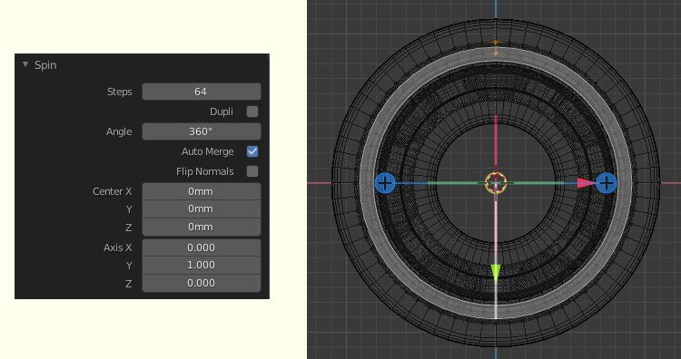
NUM/ into local view and press Alt-A to deselect all vertices.
Press C for Circle select and select 4 vertices shown. Because we are in Wire view the back vertices will also be selected.
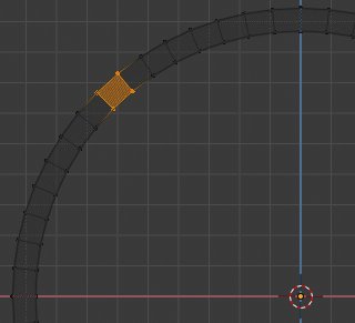
Press X to delete the 8 vertices leaving an opening in the Circlip
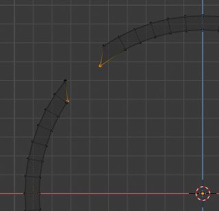
Circle select the vertices either side of the opening on the inside edge of the Circlip.
Rotate the vertices -5 degrees. As we are in front view and haven't set an axis they will rotate relative to the screen.
The two ends of the Circlip are currently open and require the addition of faces.
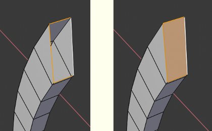
Alt-LMB Loop select the edges around one of the openings then press F to insert a face.
Repeat this on the other opening.
To make sure the mesh has consistent Normals press Shift-N
In Edge Select mode Shift-Alt_LMB select the 4 edge loops shown.

RMB to open the Context Sensitive Menu and choose Bevel Edges.
In the Bevel Panel set:
- Width: 0.05
- Segments: 1
A chamfer will be created on the selected edges.
Tab into Object Mode
Go to Side View Num3 and select Z Wireframe
We now need to mirror it across to the other side of the Bearing.

With the Circlip selected press Shift-D to duplicate it then Esc to leave it in place.
Press Ctrl-M to mirror the duplicated circlip, then Y for the axis and LMB to accept.
We now have all te components of the 608 Bearing. The last thing will be to change the names of the Circlips.
In the Outliner double click on 608-Race.001 and change its name to 608-Circlip.001.
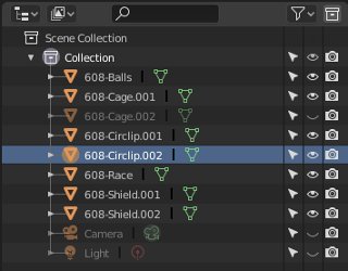
Then double click on 608-Race.002 and change its name to 608-Circlip.002.
The two Circlips are now created and positioned within the circlip groove of the bearing race.

That completes the modelling of the components for the detailed bearing. In the outliner open the eye icon for all the parts to bring them into view. (If the components don't appear you may still be in local view, try pressing Num/ to close local view) Rotate the view to see your work.
The Dust Shields covers most of the components so you may want to hide one of the dust shields (Outliner eye icon).

Press Ctrl-S and save your work.
3D Computer Graphics Using Blender 2.8 - Modelling Methods, Principles & Practice
If you are enjoying and learning from these tutorials, you might be interested in getting a copy of my book.

The book contains both reference chapters and practical guidance, taking a new or experienced user through the process of modelling a complex spiral staircase from adding the first circle object to finishing with a camera fly through of the completed scene.
The Book contains:
Pages: 506
Images: 915
More details and a chapter by chapter breakdown of the books contents can be found on my Illustration website


