Modelling a Propeller Blade
As part of my modelling my Spitfire cutaway model I needed to be able to be able to model a propeller for the aeroplane. As propellers have a fairly complex geometry changing both profile and twisting along the blade I thought it might be useful to produce a tutorial of the process I used.

I am assuming you understand the basics of modelling in blender, if you dont I would suggest you complete the 608 Bearing tutorial first which explains the basic principals of mesh modelling and the use of Blenders hot keys in detail.
The process used in this tutorial will be to create a stack of cross sections through the propeller blade and then skinning the cross sections to give the propeller profile. Propellers were traditionally designed using a series of cross sections and plans can be found on the internet or from specialist engineering blueprint suppliers.

The original plans were quite complex giving a significant amount of detailed dimensions together with the varying angles of each cross section. To help with this tutorial I have created a simplified plan containing only the necessary cross sections and placement lines, based on a simplified propeller design. The plan can be downloaded from << here >>
When you first open Blender you will be presented with the default screen containing a camera, lamp and cube object presented in a 3D view. Press Num-Pad 1 to go into front view, Num-Pad 5 to go into Orthographic view and press N to open the Properties Shelf.
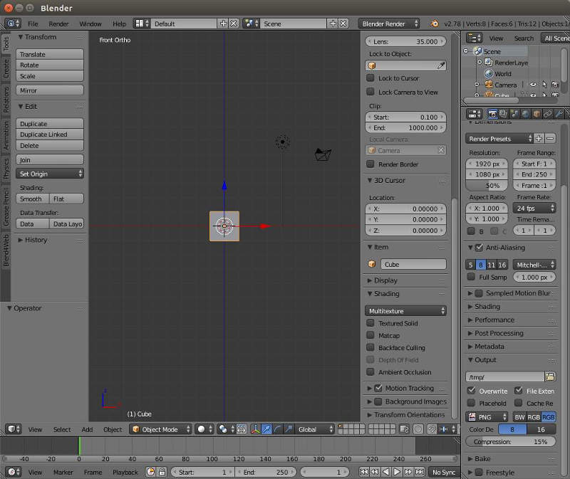
To add a background image as a reference to model from, at the bottom of the Properties Shelf select Background Image and add the Propeller001 image. It is okay to have the plan axis set to all views as all the modelling using the plan will only be carried out in front view.
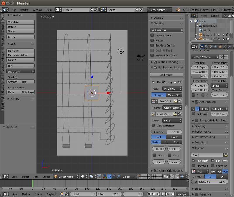
With the plan in the 3D view X delete the default Cube and zoom in to the bottom section. Place the mouse directly over the cross made up from the centrelines that run through this section and press the Right Mouse Button RMB This will place the 3D cursor on the correct point to insert the curve that will make up the first section.
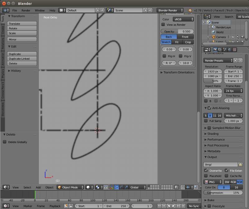
Press Shift-A to add a new object and click on Curve >> Circle to add a Bezier Circle and in the operator panel click aligned to view. The Bezier circle will surround the bottom section.
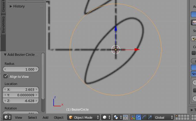
TAB into edit mode and press R then 45 to rotate the curve 45 degrees.
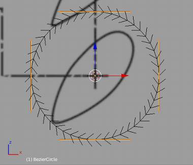

Shift-RMB Select the the two control points that run parallel with the longest edges and press S to scale them onto the background image section. RMB select the bottom control point and Press G (Grab) and move it onto the propellers trailing edge. Adjust the handles to fit the curve to the section profile.


RMB select the top control point and then G to move it onto the leading edge. Fine adjust the control handles to fit the line of the propeller section. You should now have a Bezier Curve that matches the propeller section.


Tab into Object Mode and then press Shift-D to duplicate the curve, moving the duplicate curve so it's object centre lies directly over the corresponding centre lines of the propeller image. Tab back into Edit mode press A to select all the control points, you may need to press A twice if a control point is active. Press R then X then 90 to rotate the control points 90 degrees on the X axis. The Bezier section will now be placed on the bottom of the propeller stack.


Tab back into Object Mode and RMB select the Bezier section that lies over the Bottom Propeller Section. Press Shift-D to duplicate the section and then G followed by Z to move the duplicate on the Z axis and position it's origin directly over the centre lines of the second section.


Tab into Edit Mode and position the curve handles so the curve lies over the image below. It is important that the control points are in a similar location to the section below and the control points that correspond to the leading and trailing edges are placed accurately on the leading and trailing points of the section. Accurate placement of the control points is important as it will influence how well the propeller is skinned during the final stages of the process.
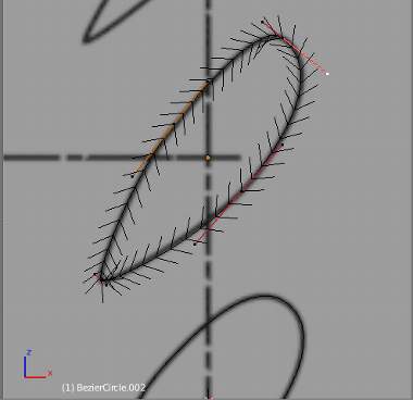
Tab back into Object Mode and press Shift-D then X to duplicate the section and move it on the X axis placing it on the corresponding centre lines of the propeller image it on the propeller stack.

The second section can be placed exactly over the first section by Ctrl-C copying the X location in the Transform panel of the Properties Shelf and Ctrl-V pasting it into the X location of the second section.

As with the first section Tab into Edit mode select All and Rotate on the X axis 90 degrees.
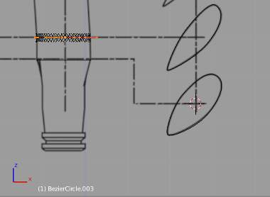
Repeat this process to shape and position the curves of all the other sections.
For the moment we are finished with the background image so the Background Image option can be deselected to remove it from view.
Once all complete you will have a stack of sections placed one above the other. In Object Mode Shift-RMB select each section and go into Top View Num-Pad-7 which shows how complex the geometry of the propeller is.
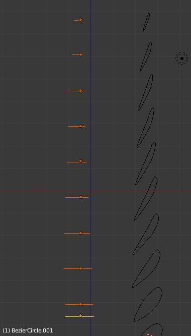
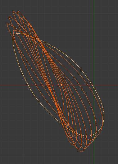

With all the curves of the stack selected they can now be joined into a single curve object by pressing Ctrl-J
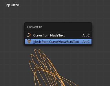
It isn't possible to skin a stack of Bezier Curves in Blender so they must now be converted to a mesh object This is done by pressing Alt-C and choosing 'Mesh from Curve'
Rotate the view to a convenient angle to see all the sections and Tab into Edit Mode, Press A to select all and then W to open the specials menu, choose Bridge Edge Loops and a skin will be created over the sections.

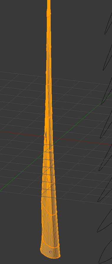
To detail the bottom of the propeller Alt-RMB select the botton loop of vertices and Extrude them on the negative Z axis to the first direction change.

We now need to convert this profile to a circle. Fortunately this is possible using an add-on called Loop Tools which will need to be activated in the Preferences Panel (search Google if you are unsure how to do this).
Press W and select Loop Tools >> Circle which will change the propeller section profile to a circle. Press S to scale the circle and scale it's diameter to match the background image.
Repeat the Extrude and scale process to complete the bottom profile of the propeller.
In side view Num-Pad-3 reactivate the background image to show the height of the propeller and zoom in to the top of the propeller. Alt-RMB select the top section and Extrude it on the Z axis to the bottom of where the curve profile starts.

Using proportional editing Shift-RMB select a vertice from the middle of each side of the propeller section and using proportional editing press G to grab the vertices and move them in the Z direction to shape a curve on the end of the blade.
The open end will now need to be closed. this can be done by ALT-RMB selecting the open top loop of vertices and then Shift-RMB deselecting the leading and trailing edge vertices. This will leave two disconnected rows of selected vertices that can be joined by pressing W and selecting Bridge Edge loops.

Add an edge loop across the newly created faces by pressing Ctrl-R and Grab these vertices moving them slightly on the Z axis to shape the end profile.

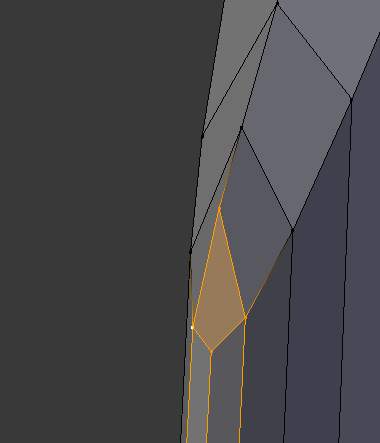
A Face can be added to the open corners by Shift-RMB selecting the 4 vertices and pressing F for Face.

The propeller blade can be further refined by adding a smooth shading to the faces and an Edge Split Modifier.
If a lower polly propeller is required vertical edge loops could easily be removed from the flatter sections of the propeller blade by Alt-RMB selecting loops and then deleting them by pressing X and choosing edge loop.
A further refinement could be the addition of a sub surface modifier which would further smooth the propeller.
To complete a four blade the propeller assembly Shift-D to copy the blade and Rotate it 90 degrees around the centre point of the propellers rotation, repeat that twice more for the four blades.
I hope you have found this tutorial useful and I would be interested to know if the technique is used in any future aeroplane models.
3D Computer Graphics Using Blender 2.8 - Modelling Methods, Principles & Practice
If you are enjoying and learning from these tutorials, you might be interested in getting a copy of my book.

The book contains both reference chapters and practical guidance, taking a new or experienced user through the process of modelling a complex spiral staircase from adding the first circle object to finishing with a camera fly through of the completed scene.
The Book contains:
Pages: 506
Images: 915
More details and a chapter by chapter breakdown of the books contents can be found on my Illustration website


