Drawing the Cross Section
This is an updated version of the 608 Bearing Tutorial first written for Blender 2.4x series back in 2007 and then also updated for Blender 2.6+ and newer versions. The initial idea was to demonstarate that Blender could be used for modelling objects with a high degree of precision.
With the introduction of Blender 2.80 significant changes have been introduced to both the interface and the modelling tools. This has meant there are significant changes to the way the bearing model is constructed in this tutorial compared to the past two versions.
his tutorial introduces some of the basic modelling techniques and tools that can be used to build accurate components. Two bearings will be covered in the tutorial, a detailed model with a large number of vertices and a low detailed one with substantially fewer vertices for use on slower computers or for use in large assemblies. The low detailed model will still be dimensionally accurate.
First of all, I think a brief description of what we are about to model and how we will go about it is in order. Its always better to plan what you are doing before you start, rather than leaving it to chance as you work through your ideas. This model won't be used to manufacture the bearings so I am only concerned with the internal diameter, external diameter and width of the bearing being accurate, the rest is open to some artistic interpretation.
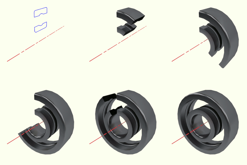
The method to create the shell of the bearing will be to draw a cross section of the inner and outer race relative to the centre axis of the bearing and then spin this through 360 degrees.
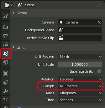
Before starting to model we need to change the units we are modelling in to reflect the small size of the bearing. By default if we move something in Blender by a unit of 1 we have moved it Blenders vertual world the equivalent of 1 metre. The bearing is tiny in comparison and we would have to input 0.007 for the width of the bearing. To make things easier we can change the unit of length to millimetres.
In the properties panel in the bottom right of the screen select the World Tab and expand the Units panel. Click on the drop-down for Length units and select Millimeters.
NOTE: Because we are now modelling the bearing to scale within an early version of Blender 2.80, many of the parts have a sub mm thickness which may cause artefacts within the viewport. In a number of the screen shots you will see back face vertices showing through when in solid view.
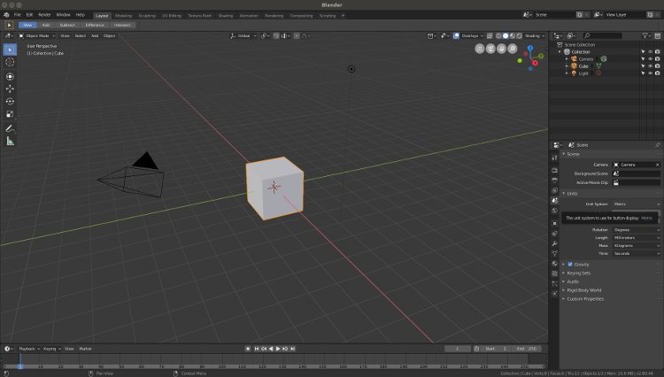
As we progress through the tutorial the keyboard and mouse actions will be shown in Bold type. In the 3D Viewport, the main work area when modelling in Blender, you will be presented with the 3D view looking onto a cube object.
In the top right corner of the 3D viewport, the axis indicator shows the directions of the axis views axis.
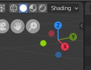
If you LMB click and drag the circular ends of the axis indicator the view will rotate corresponding to the movement.
Also press and hold the MMB (middle mouse button) anywhere in the view and drag the mouse around to rotate the viewing direction, the other sides of the cube will then be seen.
You can pan the view by holding down the Shift key whilst pressing the MMB and moving the mouse.
You can switch to top view at any time by pressing NumPad-7 (Top View). If you loose your cube from the view you can retrieve it by pressing the Home key.
Pressing Num-Pad-5 switches between orthographic and perspective views.
When we draw our bearing we need to orientate the model so the front face of the bearing is shown when we press the front view. The first part of the process is to draw a section through the bearing perpendicular to the front face, therefore we need to draw on the side view.
Press NumPad-3 (Side View) The the position of the cameras and light will change in the view and the coordinate arrows will change to reflect the different axes positions.
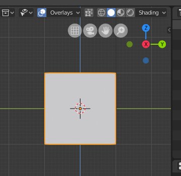
We need an object to build our model on but the Cube isn't very useful for the bearing so we will delete it.
Press the X key to bring up the delete menu and accept the pop up menu option.
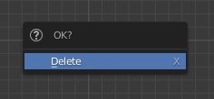
The cube will be removed from the screen leaving the 3D cursor in the centre of the global coordinates. Cursor position x 0.0000, Y 0.0000, Z 0.0000

In order to draw our bearing we need an object to represent the bearings cross section.
Make sure you are still in side view NumPad 3 then press the Shift-A to bring up the Add Menu, as we are adding a mesh object, move the mouse over "Mesh", another list of options will appear, click on "Plane".

A Plane will be created, centred around the cursor, initially side on to the side view. In the bottom left of the viewport the Add Plane panel will also appear, you may need to expand the panel to see all its settings. Select align to view and the plane will be aligned to the side view. However the Plane will now have a Local rotation different to the Global Axis. To correct this press Alt-R to clear the rotation
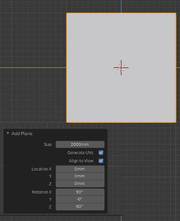
Currently the size of the plane is 2 metres and needs to be reduce to to the size of the cross section of the bearings inner and outer race.

In the size field of the Add Plane panel change 2000mm to 7mm.
The plane will now be 7mm square, you will need to zoom in to see it by rotating the mouse SW (Scroll Wheel). If the plane disappears from view you may need to change the Views clipping range. Press N to access the View panel on the right of the 3D Viewport and change Clip Start from 100mm, to 0.1mm
The plane is located directly on the world origin at location 0,0,0 and the panels origin is also at 0,0,0
We need to move the plane to the location of the top section of the bearing race, but without moving its origin.
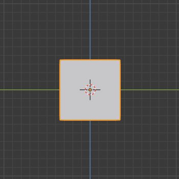
Tab into Edit Mode and with all the vertices selected press G for grab, then Z to constrain the movement to the Z-axis and followed with 7.5 for the vertical distance. (3.5mm = 1/2 the height of the plane plus 4mm for the radius of the bearings inner bore).

The bottom of the plane will now sit 4mm above the centreline of the bearing, which when spun around the Y-axis will leave a bore of 8mm.
In order to see the dimensions of the edges we are creating Edge Length needs to be enabled.
To the right of the 3D Viewports Header bar LMB click on Overlays. A panel will open below containing a number of viewport options.
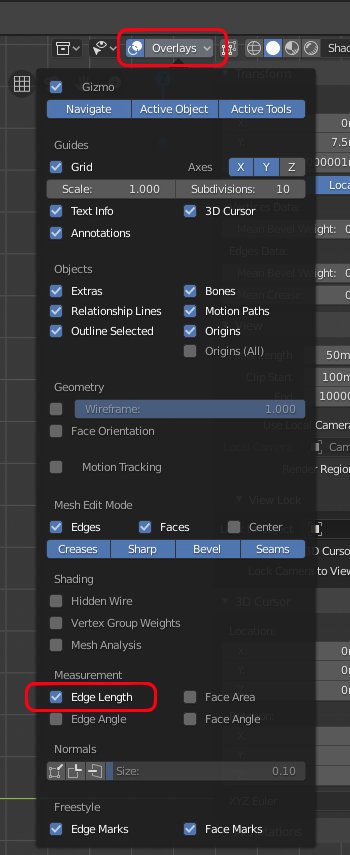
three quarters of the way down the panel LMB click Edge Length to enable it.
When you move the mouse away from the panel it will close.
We now need to split the plane into two rectangles representing the inner and outer race.
Press Ctrl-R for Loop cut and move the mouse towards the left edge, a yellow cut line will show across the centre of the plane, then press the number 2 which will create 2 evenly spaced cut lines. Press Enter to accept the two loop cuts then Esc to prevent them from moving from equal distances to the planes centre.
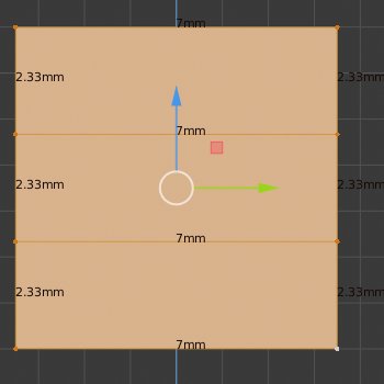
On the left hand side of the 3D Viewports Header bar LMB click to enable Edge Select

Move the mouse over the left hand central edge and LMB click to select it, all other edges will be deselected. move the mouse over to the right hand central edge and Shift-LMB select that edge. Both central edges will be selected.
Press X on the keyboard and from the Delete pop-up menu select Edges.
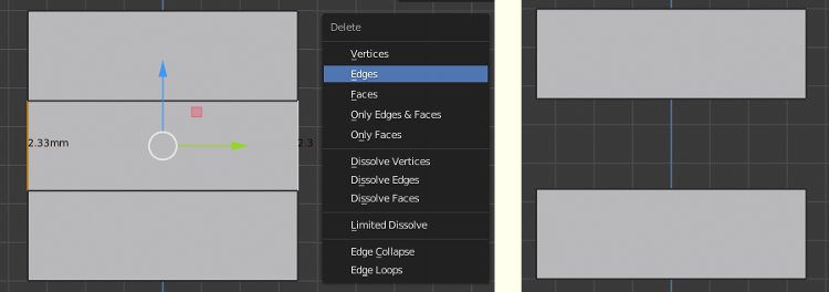
Both edges and the centre face will be deleted leaving two faces representing the inner and outer race.
The next stage is to add the groove that the bearings run in.
To the left of the 3D Viewport Header Bar enable Vertex Select.

Press A to select all vertices, then press Shift-S to open the Snap Pie-menu and select Cursor to Selected. This will place the 3D cursor at the centre of the inner and outer bearing race.

On the centre of the 3D Viewports Header bar LMB click the Pivot Point drop-down and select 3D Cursor.

This will position the 3D Cursor at the centre point for the ball bearings.
The Ball Bearings have a diameter of 3.95mm so we need to add a circle centred on the 3D Cursor with a radius of 1.975mm.
Press Shift-A and select Circle from the pop-up menu. This will add a circle centred on the 3D cursor. The circle may not be visible as it will have a radius of 1000mm and be aligned to top view. In the Add Circle panel that opens in the bottom left of the 3D viewport change Vertices to 64, Radius to 1.975 and enable aligned to view.

You will now have a 64 vertices circle centred on the inner and outer race.
We now need to rotate the 4 vertices indicated so the sit on the inner face of either the outer race or inner race.
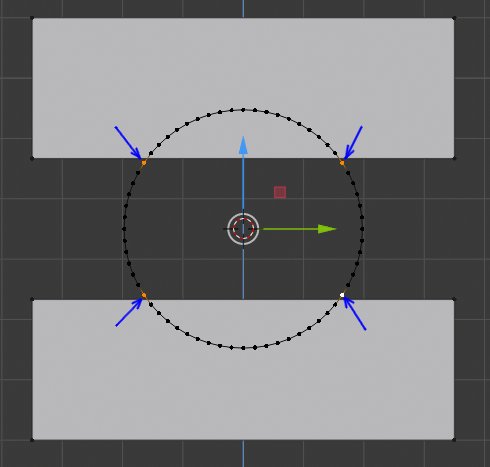
Select one of the vertices on the inner face of the outer race and in the Transform tab of the N Panel note the Z location which is 8.6667.

LMB select a vertex from the circle that lies just below the inner face of the outer race. Press R to rotate it, as we are already 3D Cursor centre point mode the rotation will be from the centre of the circle.

Move the mouse until the Z location in the transform panel also reads as 8.6667. Moving the mouse further away from the centre of the bearing or holding down Shift whilst moving the mouse gives finer adjustment.
Carry out this process for all 4 vertices that lie close to the inner faces of the inner and outer races.
Press B and Box Select the vertices that now lie between the inner and outer races and press X to open the Delete menu. Select vertices to remove them.

Go into Edge Select mode and LMB select the two edges representing the inner face of the inner and outer races. Press X and from the Delete menu choose Edges. the two edges and both faces will be removed.
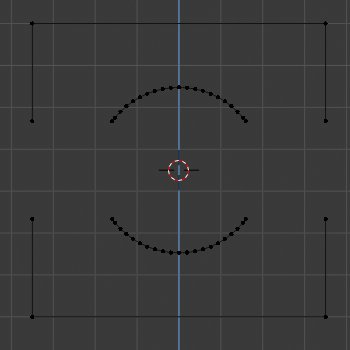
Go Back to vertex select mode.
Shift-LMB Select the two corresponding vertices between the outside edge of the outer race and the outer vertex of the outer race groove and press F to insert a new Edge.
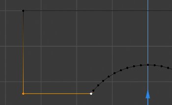
When only 2 vertices are selected F will create an edge between them.
When more than 2 vertices connected by edges are selected a new face will be created
Move the mouse close to a vertex on the outer race and press L for Link Select. All the vertices of the outer race will be selected.
Press F and a face will be created within the outer race. A new edge between the groove and outer wall that was previously open will also be created.
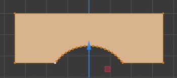
Repeat the above process for the inner race.
With both inner and outer race now being complete Shift-LMB select the 4 corner vertices.
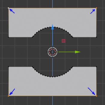
RMB click within the 3D Viewport to open the Context Sensitive menu.
Choose Bevel Vertices from the list.

Move the mouse slightly to add a slight chamfer on the corner, the Bevel Panel will open in the bottom left of the 3D Viewport.
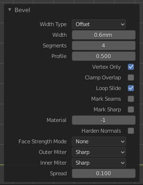
Set Width to 0.6mm as we need a 0.6mm radius on the edges of the bearing and set Segments to 4 to give a rounded corner.
We now have the basic profile of the inner and outer race.
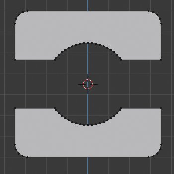
In part 2 we will add the detail of the rebate to hold the bearings shields and the circlip grooves.
3D Computer Graphics Using Blender 2.8 - Modelling Methods, Principles & Practice
If you are enjoying and learning from these tutorials, you might be interested in getting a copy of my book.

The book contains both reference chapters and practical guidance, taking a new or experienced user through the process of modelling a complex spiral staircase from adding the first circle object to finishing with a camera fly through of the completed scene.
The Book contains:
Pages: 506
Images: 915
More details and a chapter by chapter breakdown of the books contents can be found on my Illustration website


