Modelling the Bearing Cage
When we inserted the UVsphere that formed the ball bearings it was important to ensure that one of the poles pointed to the centre. By doing this it has left us with the rings of the ball running perpendicular to the to the bearing centre axis and this allows us to extract the geometry from the surface of the UVsphere to form the inner profile of the bearing cage. This will become a little clearer as we work through this part of the tutorial.

In front view select the balls, as the bearing race will get in the way of our view select local view Num/. This will remove everything from view except the selected objects.

With only the balls in view, zoom in and pan on to the top ball, SW (scroll wheel) to zoom, Shift MMB to pan.
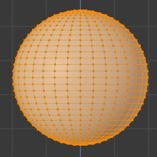
Tab into Edit Mode and go into solid view Z.
Deselect all vertices Alt-A then Link Select the vertices of the top Ball, you do this by holding the mouse cursor close to a vertex on the top ball and pressing L.
We need to snap the 3d Cursor to the centre of this ball. Press Shift-S and choose Cursor to Selected.

Box select B 6 rings of vertices starting from the centre ring and moving towards the bottom of the sphere.
We will copy these vertices and turn them into a new object, they will then form the inner part of the bearing cage.
Press Shift-D to copy the vertices, then press Esc so they aren't moved from their original position.
A new set of vertices has been created on top of the sphere. With these still selected press P (part) to separate them from the 608-Balls object.
A new object has now been created and removed from the current Edit Mode selection.
Tab into Object mode, the new cage object is on top of the top UVsphere.

LMB click over the cage to select it and its outline will be highlighted.
Tab back into Edit Mode.
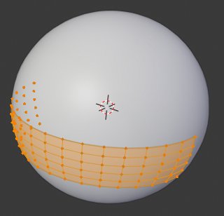
Currently the vertices of the cage are sitting on the surface of the ball which would stop the bearing from turning, so we need to add some clearance. To achieve this we will scale the cage from the centre of the top ball bearing.
With all A the cage vertices selected and the Pivot Point still set to 3D Cursor and the 3D Cursor centred on the top bearing, we can scale S the cage 1.02 This will give you a clearance of 0.0395 between the ball and the cage. ((Diameter * 1.02) - Diameter) / 2

We have now got the inside profile of the cage but we need to add thickness to it. We could simply Extrude a new set of vertices and then scale them from the centre however we would need to work out a scale factor. Instead Blender has the ability to scale all faces in the direction of the face normals (see Blender Wiki for explanation of Normals). As we are scaling individual vertices then we only need to use the thickness as the scale factor.
With all the vertices selected extrude E then press Esc so the new vertices don't change position. Press Alt-S to scale along normals and 0.3 for the thickness then press Enter. The cage is now 0.3mm thick.

Press Num/ to come out of local view for the ball bearing and cage then press Num/ again to go into local view for only the cage then go to Top View Num7
As we have created the thickness of the cage by scaling in the direction of the faces, and the new end vertices are no longer on the centreline of the bearing. With the cursor still on the centre of the top ball and Pivot set to 3D cursor, select the new end vertices.

You will need to select the "Show Whole Scene transparent" button on the viewport Header.

Shift-LMB to select, then scale S in the Y axis to 0.
It may be easier to select all the end vertices of the cage as those that are already on the centreline won't move. B box Select vertices within the area outlined below, then with the pivot set to 3D Cursor, Scale Y-axis to 0

All the end vertices will now lie on the centre line.
We now have the cage form that surrounds the bearing but if we Spin-Dupli this we will still be missing the section that bridges between this ball surround. Therefore before we Spin-Dupli this section we need to locate vertices so the bridging section when formed is 0.3mm thick.
In top view select the outer most vertex and Extrude it -0.3 in the Y axis. This vertex will be the reference point to cut a new row of vertices.
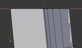
For the knife to work from this vertex we now need to create a face as the knife only snaps to vertices that belong to a face.
With the extruded vertex still selected, Shift-LMB select the two top edge vertices closest to the new vertex and press F to add a new face.
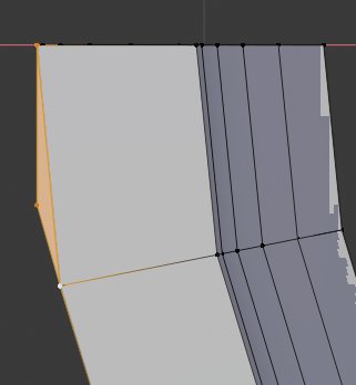
Press K to open the knife tool. The mouse icon will change to a knife.
Move the knife close to the reference vertex that was extruded from the end vertex of the cage, a green snap opint will appear over the vertex. press Z so the knife cuts through both sides of the mesh then press C to constrain the cut. LMB click over the reference vertex then move the mouse to the left of the cage. the movement will be constrained to the horizontal. Press LMB to accept the cut, a red cut line will appear, then Enter to accept the cut.

A new line of vertices will be cut across the cage 0.3mm from the centreline of the bearing.

The reference vertex 0.3mm from the left hand edge can now be deleted LMB select the vertex and press X to delete it.
Deselect "Show Whole Scene Transparent" on the Viewport Header.
Select the Edge Select icon on the left of the Viewport Header.

Shift-LMB select the 4 edges shown between the back edge and cut line.
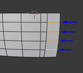
Press X to open the delete menu and choose Edges from the drop-down. We have now created an opening where we can bridge between the duplicated cages,
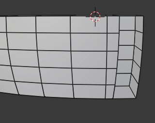
Repeat the above process on the other side of the cage.
The loop of edges closest to the opening is too close to allow the edge to be bevelled. To move it away, place the mouse over one of the vertical edges and press Alt-LMB for loop select.
Press R for Rotate then Z to constrain the rotation to the Z-axis and 5 for the 5 degree rotation. Click the LMB to confirm the rotation.

Repeat the process on the other side of the cage.
Note: it will be necessary to use a rotation of -5 on one side of the cage.
With the cage around the top bearing complete we now need to Spin Duplicate it around the other ball bearings.
Tab into Object Mode press Num/ to come out of Local view and press Num1 to go into front view.

Ensure the 3D cursor is still on the bearings Origin, if not Tab into Object Mode and press Shift-S to open the snap menu and select Cursor to Selected. The 3D Cursor will jump onto the cages Origin which is located at the centre of the bearing race.
Tab back into Edit Mode and press Num/ to take the cage back into local view.
LMB click on the Tool Bars Spin widget.
In the Spin Panel set Steps to 7, select Dupli, set Axis Y to 1 and Axis Z to 0

On the top cage, Alt-LMB select the edge loop surrounding the right hand opening.
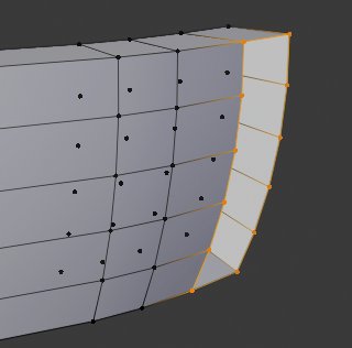
On the first duplicate to the right of the top cage Shift-Alt-LMB select the edge loop to the left of that cage.
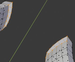
Press Ctrl-E to open the Edge menu and choose Bridge Edge Loops.

new faces and edges will now bridge between the two cages.
To break up the long faces and provide vertices to form the clasp that holds the two cages together, move the mouse over one of the edges and press Ctrl-R for loop cut, then press 3 to cut 3 evenly spaces loops, then LMB click to accept the loop cuts followed by Esc to prevent the loops from sliding along the faces.

Shift-Alt-LMB select the loops of vertices that join the bridged section to the cages.
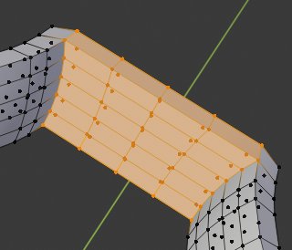
Spin the selected vertices around the bearing centre using the same process as described for the cage above.
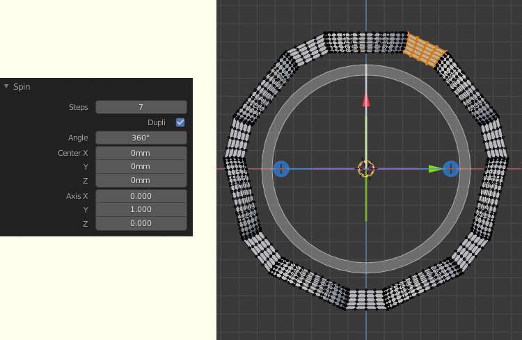
Finally select all vertices A and then open the Context Sensitive menu by RMB clicking anywhere within the 3D Viewport and select Remove Double Vertices.
The join between the curved bearing location of the cage and the bridging section has a bevelled rather than sharp internal edge.
To produce this go into Edge Select mode (Edge Icon on the Viewport Header) andShift-Alt-LMB select each of the edge loops on the junctions between the cage and bridged sections. In total there will be 14 Edge loops selected.

Open The Context Sensitive menu clicking the RMB. As we are now Edge Select mode the menu will show the available edge tools. Select Bevel Edges and move the mouse slightly to start a Bevel then LMB to accept.
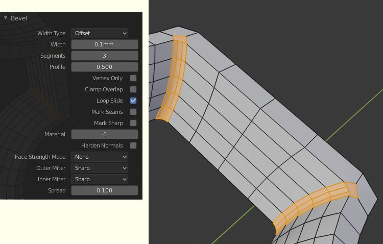
In the bevel Panel set Width to 0.1 and Segments to 3. The junction will now have a rounded bevel.
The first cage is now almost complete and needs to be copied and mirrored to form the basis of the opposite cage.
Tab into Object Mode then press Num3 to go into side View.
With the first half of the cage selected press Shift-D to copy it then press Esc to leave it in position.
Press Ctrl-M to mirror the copied cage then press Y for the mirror to work on the Y-axis then Enter to accept.
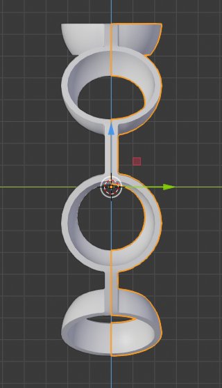
Because the 3D Cursor is sitting on the bearings centre the second cage will be flipped to the other side of the bearing.
The two cages have been created from the 608-Balls object and have therefore inherited the names 608-Balls.001 and 608-Balls.002

We now need to give the cages a meaningful name. in the Outliner at the top right of the screen double LMB click on 608-Balls.001 to allow you to edit the name. Change its name to 608-Cage.001
Then double LMB click on 608-Balls.002 to allow you to edit the name. Change its name to 608-Cage.002
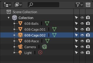
In the 3D Viewport LMB click on 608-Cage.001 then press Num/ to go out of local view and press Num/ to go back into local view with only 608-Cage.001
We need to complete this cage by adding a chamfer to the top and bottom edges.
Press Alt-A to deselect all edges then using Shift-Alt-LMB loop select work your way around the top and bottom edges of the cage until you have 4 compete edge loops all the way around the cage.
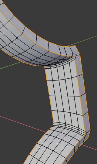
It is worth going into Wireframe view to check the 4 loops are continuous.

Press Ctrl-B and add a chamfer to the loops using the settings in the image below.

OB:608-Cage.001 is now complete.
If you haven't already done so press Ctrl-S and save your work.
In part 5 we will add the clasp to 608-cage.002 that secures the two half cages together.
3D Computer Graphics Using Blender 2.8 - Modelling Methods, Principles & Practice
If you are enjoying and learning from these tutorials, you might be interested in getting a copy of my book.

The book contains both reference chapters and practical guidance, taking a new or experienced user through the process of modelling a complex spiral staircase from adding the first circle object to finishing with a camera fly through of the completed scene.
The Book contains:
Pages: 506
Images: 915
More details and a chapter by chapter breakdown of the books contents can be found on my Illustration website


