Modelling the Cage Retaining Clasp
With 608-CageA now complete its time to go back to 608-Cage.002 which we copied and mirrored from 608-Cage.001 before the chamfers were added.
In the outliner click on 608-Cage.002, de-select the Eye icon to close the Eye Icon for all other objects so only 608-Cage.002 is visible in the scene.

When we originally mirrored the cage from 608-CageA, we effectively applied a scale factor of -1 in the Y axis. Press N to open the Transform Properties window, You will see Scale Y: -1.000. To clear this back to Scale Y:1.000 we need to apply the scale to the object. To do this press Ctrl-A and accept "Apply Scale and Rotation". If you had simply changed the number in the Transform Properties window to 1 the cage would have flipped back to the other side of the bearing.
In Edit Mode select all and set Shading to Flat. This will make the next stages of modelling easier to visualise.
We need to square up the outer edges of the central face on the bridging section. This is best done on the bottom bridging section because it is aligned to the World Coordinates. This section can then be copied to replace all of the other bridging sections. Therefore all but the bottom bridging sections can be deleted.
In Vertex select mode, Alt-LMB Loop select the three edge loops set in from the spherical sections of the cage.

Don't select the loops on the bottom bridging section.
Press X and choose vertices to delete the unnecessary bridging sections.
Tab into Edit Mode and go into solid view Z.
The clasp is easier to model without the central edge loop of the bridging section.
To remove it, Loop Select the central edge loop and press X for delete and this time choose Edge Loops from the Delete menu.

The edge loop will be removed but the faces will be preserved.
Select an edge loop that was next to the removed central edge loop and move it G (grab) along the X axis until the vertex on the back face is 0.3 mm from the edge loop on the curved section of the cage. Do the same on the opposite edge loop.

the bottom face of the bridging section isn't currently square because it was formed from the the opening in the spherical section of the cage. To square up the face go into Bottom View Ctrl-Num7 and select the vertex that is 0.3 mm from the cage on the back edge. Copy Ctrl-C the X location in the Transform properties panel.

Select the opposite vertex and Ctrl-V paste the copied location into the X location of the of the Transform Properties panel.
The edge will now be perpendicular to the front and back of the cage.

Repeat this on the other side of the bottom face, so the face becomes square.
Select a vertex on the back edge of the bottom face and Shift-S snap the 3D Cursor to it using Cursor to Selected.
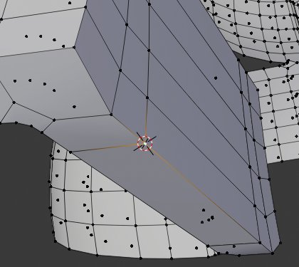
Select the bottom face and Scale it on the Z axis to 0 this will level it up to the X-Y Palne at the Z depth of the 3D Cursor.
Click on the Spin icon in the Tool Shelf.

LMB click on the blue widget to open the Spin Panel.
Set Steps to 7, Angle to 90 Axis-X to 1 and Axis-Z to 0
the face will spin through 90 degrees.
With the face still selected Extrude it 0.3mm

Select the vertex indicated and snap the 3D Cursor to it. This becomes the next rotation point.
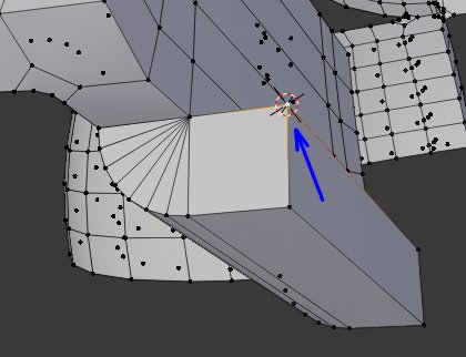
Reselect the face to spin another 90 degrees.
Click on the Spin Icon then LMB click the spin widget.

In the Spin Panel Set Steps to 7, Angle to 90 Axis-X to 1 and Axis-Z to 0
The face will again spin through 90 degrees.
With the face still selected Extrude along the Z axis 1.05 mm

Select the two short edges of the extruded face.

press Ctrl-E to open the Edge Special menu and select Bevel Edges.
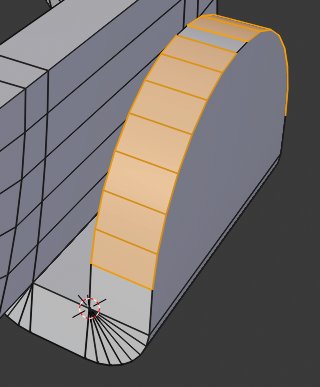
Move the mouse slightly then LMB click to open the Bevel Panel.
Set Width to 0.8 and Segments to 7.
Carefully select all the faces of the bridging section as shown below.
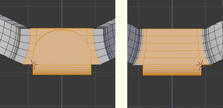
A word of Caution
The following spin operation when performed on my computer using Blender 2.80,
has caused Blender to shut down unexpectedly on a number of occasions
Shift-S to save your work before proceeding.
Go into front view Num1.

Tab into Object Mode and snap the 3D Cursor to the Origin at the centre of the bearing, Shift-S Cursor to Selected.
Tab back into Edit Mode.
Click on the Spin Icon of the Tool Panel and LMB click the blue spin widget.
In the Spin Panel set:
- Steps: 7
- Dupli: selected
- Axis-Y: 1
- Axis-Z: 0
The bridging section including the clasp will be duplicated around the cage.

To finish off the spin, in vertex select mode Select All then RMB click to open the context Sensitive menu and select Remove Double vertices.
Also to ensure all Normals are pointing to the outside of the cage press Shift-N to activate Make Normals Consistent.
As with 608-Cage.001 we now need to add the four edge chamfers around the inner and outer edges. Again checking in wire frame mode may help to ensure the edge loops are continuous.


In Edge Select mode RMB click to open the Context Sensitive menu and select Bevel Edges. Move the mouse slightly then LMB click to open the Bevel Panel.
In the Bevel Panel set Width to 0.05 and Segments to 1.

A chamfer will be created around the selected edge loops.
608-Cage.002 is now complete.
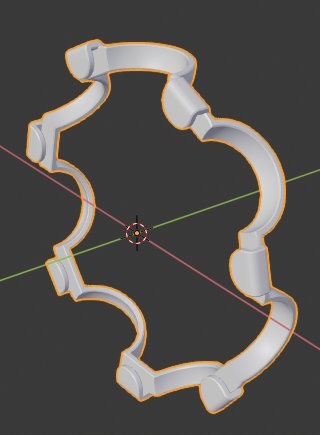
If you haven't already done so press Ctrl-S and save your work.
In part 6 we will model the dust shield and circlip.
3D Computer Graphics Using Blender 2.8 - Modelling Methods, Principles & Practice
If you are enjoying and learning from these tutorials, you might be interested in getting a copy of my book.

The book contains both reference chapters and practical guidance, taking a new or experienced user through the process of modelling a complex spiral staircase from adding the first circle object to finishing with a camera fly through of the completed scene.
The Book contains:
Pages: 506
Images: 915
More details and a chapter by chapter breakdown of the books contents can be found on my Illustration website


